Optek® Criterion MAX
Operation and Maintenance Manual
Version 1.70 Rev D | |
The information in this manual is subject to change without notice and is provided “as is” with no warranty. Intuitos, LLC specifically disclaims liability for any direct, indirect, special, incidental, or consequential damages in connection with the use of this material. Copyright © Intuitos, LLC. All rights reserved.
| Complete familiarity with your equipment and its operation is the
most effective way to ensure the best results in your surfaced lenses
and the safest work environment. Please read this entire manual
carefully before attempting to install or operate the equipment. |
Congratulations on your selection of the Optek® 435 Criterion MAX Surfacer! As an owner of Optek equipment, you have the significant advantage of a partnership with a leading manufacturer of advanced ophthalmic lens processing systems.
Safety
Operator safety is of the utmost importance. To ensure the highest level of
safety, anyone operating the equipment must be thoroughly trained in its
operation and safety features. Special notations and symbols are used in this
manual to help you identify and understand potential hazards:
 |
General Danger — A risk of injury to personnel if
instructions are not followed. |
 |
General Mandatory Action — A particularly important point or
a risk of damage to equipment if instructions are not followed. |
Protective Covers
When using the equipment with all covers in place, the operator is protected
from any contact with electrical contacts and wiring. All moving parts, where
possible, are completely enclosed.
|
Never perform any maintenance or adjustments without disconnecting
the equipment from utility power. The operator should never attempt to
service the equipment. The equipment should NEVER be operated with the
door or covers open or removed. Always wear eye protection when
operating or servicing equipment. |
Chemical Hazards
All chemical products pose certain hazards including, but not limited to,
toxicity and flammability. Data should be obtained regarding the dangers, or
lack thereof, for any chemical product used in your workplace.
Material safety data sheets (MSDS) are available for all products
manufactured or distributed in the United States. Upon request, Optek will
supply copies of these for each product that we distribute. They may also be
obtained by applying directly to the manufacturers. Copies of these, or similar,
data sheets must be kept with this manual at all times. Further information
regarding the safe handling of chemical products, especially as regards to local
regulations, may be available from the responsible regulatory agency in your
country.
|
All employees who will work with or around any lubricant, slurry,
cleaning supply, or other chemical product must be required to read the
applicable safety data sheets and receive appropriate safety training.
This must be done before they are exposed to the chemical product. |
|
If your equipment dispenses alloy, you must observe special precautions.
Regulatory agencies have designated alloy blocking material as a
toxic substance. Use and disposal of alloy blocking material and other items
or substances that have come into contact with alloy blocking material are
subject to various regulations that may vary from area to area. Always consult
and comply with all applicable regulations, guidelines and laws.
IF ANY INSTRUCTIONS IN THIS MANUAL CONFLICT WITH APPLICABLE REGULATIONS,
GUIDELINES OR LAWS REGULATING THE USE AND DISPOSAL OF ALLOY IN YOUR AREA,
ALWAYS DEFER TO THE INSTRUCTIONS OF THE REGULATING AUTHORITY. |
Moving Parts and Vibration
Some equipment may have moving parts that are exposed to the operator, and
some equipment may produce vibration during operation. It is important to avoid
any contact with a machine during operation. Exposed moving parts may cause
injury, and prolonged exposure to certain vibrations has been shown to cause
health problems.
|
Do not lean or rest any part of your body on or against machinery
while it is running. Do not wear a necktie, loose clothing, or dangling
jewelry while operating equipment. Long hair must be kept securely
fastened out of the way. |
General Precautions
When working with liquids such as water, coolant, or slurry, spills are
likely. It is recommended that high-quality non-slip floor mats be used in the
working area. Operators may attend several machines simultaneously, moving
quickly among machines. Mats, therefore, must be laid out or interlocked so that
there is little or no danger of slipping or tripping.
Never attempt to move heavy equipment or containers by yourself. See your
service supervisor if a heavy item needs to be repositioned for any reason.
Never hesitate to ask for help.
Some equipment emits noise during operation. The acoustics of your lab and
the simultaneous running of machines may cause the ambient noise level to exceed
the legal maximum. Hearing protectors may be advisable or required for all shop
employees.
|
Always wear any support or protective equipment recommended by your
doctor or supplied by your employer. |
Symbols used on Optek Criterion MAX Surfacer Controls
  | Emergency Stop |
|---|
 | Power: On/Off (push-push) |
|---|
 | Interface Port: used to connect to host computer |
|---|
 | Barcode Reader Port: used to connect barcode reader |
|---|
 | Barcode Power Port: used to power barcode reader |
|---|
Warning Symbols
The following symbols may be found at various locations on your machine. They indicate the possibility of serious injury and must not be ignored.


Opening the marked panel will expose
personnel to a pinch danger from timing belts. |
Product Specifications
| Power | 120 V AC, 1 Ph, 60 Hz, 6.5 A or
240 V AC, 1 Ph, 60 Hz, 3.5 A or
230 V AC, 1 Ph, 50 Hz, 3.5 A |
|---|
| Width | 21" (53 cm) |
|---|
| Depth | 30.5" (77.5 cm) |
|---|
| Height | 54.75" (139 cm) |
|---|
| Weight | 335 lb. (152 kg) |
|---|
| Air | Max: 100 psi (6.9 bar)
Min: 80 psi (5.5 bar) |
|---|
| Some of the procedures outlined in this chapter may require the aid of an assistant. |
Proper installation of your Optek equipment is essential to ensuring optimal results. This chapter will guide you through each procedure in the installation process. You should only have to follow these steps once, but you may need to refer to them again if you relocate your Criterion MAX Surfacer.
Required Items
- 7/16" Deep well socket and driver with 12" extension
- 5/32 Allen Wrench
- Adjustable wrench
- Assorted screwdrivers
- Level
- Padded handcart
Uncrating and Positioning
- Remove the wood shipping crate.
- Carefully cut shrink wrap and remove foam wrapping.
- Using the 5/32 Allen wrench, remove one of the screws that secure the door retaining tab and loosen the other. Rotate tab until removed screw can be threaded back into its original hole.
- Open cabinet door.
- Use the 7/16" deep well socket and driver with 12" extension to remove the four anchor bolts that hold the Criterion MAX to the pallet.
| Steps 6–7 require the aid of an assistant. The Criterion MAX Surfacer is heavy! When moving or lifting, please wear appropriate supports and exercise due caution to avoid personal injury or dropping and damaging the machine. |
|---|
- Use the padded handcart to move the machine to the desired operating location.
- Set the Criterion MAX Surfacer in place.
Leveling
- The Criterion MAX has four leveling feet under the base. Use the 1/2" wrench to loosen the lock nut that is attached to the leveling feet directly above the frame.
- Place the level across the Criterion MAX's top hood in both the front-to-back and side-to-side directions and adjust the feet until level.
- Tighten the four lock nuts.
- Rotate the door retaining tab back into its locking position and secure with both screws.
Plumbing
Connecting to Fresh Water/Central Slurry Solenoid Valve - if equipped
| Turn off water supply at source when machine is not in use. |
|---|
- Using the 5/32 Allen wrench, remove one of the screws that secure the door retaining tab and loosen the other. Rotate tab until removed screw can be threaded back into its original hole.
- Open cabinet door.
- Run the installed 6 foot female hose assembly through the hole in the back panel and attach to water/slurry supply.
- Place the vinyl drain tube into the drain system. Your drain system should be adequately graded to prevent backups.
- Rotate the door retaining tab back into its locking position and secure with both screws.
Connecting to Air Supply
- Remove the twist tie holding the power cord and airline to the outside rear of the machine.
- Insert the end of the airline into the quick disconnect air fitting located on the rear of the machine.
- Connect the airline to a clean, dry air supply (80-125 psi/5.5-8.6 bar).
- Remove the lid and and verify that the pressure gauge on the pneumatic panel reads 80 psi.
Adjusting the Main Air Pressure
- If the main air pressure gauge does not read 80 psi then,
- Unlock the Criterion MAX’s primary air regulator adjustment knob by pulling it up slightly. It should snap up, and you should hear a click.
- Slowly turn the regulator adjustment knob until the gauge reads 80 psi.
| If decreasing the pressure ALWAYS bring the gauge to a reading below your desired pressure and then increase until you reach that setting. If the pressure is not set by increasing to it, the pressure may "bleed" down. |
|---|
- Lock the regulator adjustment knob by pushing it down until it snaps into place.
Connecting the Chiller
- Connect the cooling coil to the shop chiller lines and place it in the bottom of the bowl.
- Turn on the chiller's pump switch and slowly open the flow control valve on the manifold.
- Carefully examine the installation to verify that there are no coolant leaks.
Connecting the Computer Interface
To fully benefit from its efficient versatility, the 435 Criterion MAX should be operated in automatic mode. Automatic mode operation requires:
- A host computer
- Protocol-compatible software, such as Optek Cnet Server or Optek LensMate Lab with DevCom device communications manager.
- A hardware connection between the host and the Criterion MAX.
|
When connecting electronic devices such as computers, always turn them
off and disconnect them from utility power to prevent possible damage. |
- Connect the DB9 end of the included serial cable to the host computer.
- Connect the Twist Lock end to the Network port on the rear of the Criterion MAX's hood.
Connecting the Barcode Reader - requires optional 435SA-025 Barcode Reader w/ Stand
|
When connecting electronic devices such as computers, always turn them
off and disconnect them from utility power to prevent possible damage. |
- Connect the DB9 end of the barcode reader cable into the Barcode Data port on the rear of the Criterion MAX's hood.
- Plug the barcode reader's power transformer into the Barcode Power outlet on the rear of the Criterion MAX's hood.
Electrical Service Issues
Optek recommends that a qualified electrician install a dedicated AC service supply or junction box at a place convenient to the operating location of the Criterion MAX Surfacer. Power specifications are identified on the serial number plate located on the rear of the Criterion MAX Surfacer’s control head.
| Some of these procedures will be performed periodically as you work with the Criterion MAX, so you may need to refer to this chapter from time to time. |
After completing each of the installation procedures in Chapter 2, you must perform a few startup procedures to prepare the Criterion MAX Surfacer for operation. This chapter will guide you through each of these steps.
Powering-Up
- Connect the unit to a power source matching the specifications on the serial number plate.
- Make sure that all doors and covers are securely closed before turning on the power.
- Turn on (flip up) the circuit breaker located on the left rear of the hood.
- Turn the emergency stop switch counterclockwise until it pops up.
- Press the green Main Power button on the front panel to provide system power.
- The display will show the Model/Version screen for 5 seconds.
- The operating menu will appear automatically.
 |
| Version Screen |
|---|
Slurry System
Systems with a Slurry Pump
- Place approximately one quart (.9 liters) of clean water in the bowl.
- On the Main Menu, press "4".
- Press the "F1" key to manually turn on the pump.
- While the pump is running, carefully examine all tubes and fittings for leaks.
- Adjust the flow rate using the main control valve located on the slurry pump.
- Press the "F1" key to turn off the pump.
 |
| Manual Override |
|---|
- Open the pump drain valve and empty the water into a bucket.
| Do not allow the pump to run dry for more than a few seconds, or it may be damaged. |
|---|
- Press "F1" to turn on the pump (briefly) to remove the water from the slurry lines.
| A proper slurry level is required to maintain a steady flow to the lap tools. |
- Clean and replace the strainer and replace the drain plug.
- Add two to three quarts (2.8 liters) of slurry to the bowl.
Systems with a Fresh Water/Central Slurry Valve
- On the Main Menu, press "4".
- Press the "F1" key to manually turn on the solenoid.
- Adjust the flow rate by opening or closing the main flow control valve located on the valve assembly in the bottom cabinet of the machine.
- Make a careful examination for leaks while the valve is on.
- Press the "F1" key to turn off the pump.
| Never attempt to adjust the drain hose position while the unit is running. Disconnect all power prior to performing any type of service. |
|---|
- Make sure that the hose is not rubbing against the drive belts or pulleys.
Factory Settings
Your Criterion MAX is shipped from the factory with the following preset values:
| Material | Cycle | Orbit | Time | Pin Pressure | Speed |
|---|
| Plastic & High Index | 1st Fine | 18mm | 1:00 | 18 lb. | High |
| 2nd Fine | 18mm | 1:20 | 18 lb. | High |
| Polish | 18mm | 3:00 | 18 lb. | High |
| Polycarbonate & Trivex | 1st Fine | 18mm | 1:00 | 18 lb. | High |
| 2nd Fine | 18mm | 1:20 | 18 lb. | High |
| Polish | 18mm | 6:00 | 18 lb. | High |
The Criterion MAX Surfacer has been carefully engineered to be extremely simple to operate. This chapter will help you become acquainted with the various functions as well as help you gain familiarity with the mechanics of fining and polishing.
Control Panel Overview
There are two switches along with a key pad on the front panel:
- Emergency Stop Switch (red knob): Press the knob in to cut off all power to the unit's controls and motors. Turn the knob counterclockwise to restore power to the machine.
| The Emergency Stop switch should be left in the off position when lenses are not being processed. |
|---|
- Power Switch (green button): Press on / press off.
Version
 |
| Main Menu (finer) |
|---|
You may need to confirm the model and/or software version installed.
- From the main menu (Finer or Polisher menu), press the ESC button to display the Model/Version screen.
- The main menu will reappear after 5 seconds.
Main Menu
The Main Menu gives access to all functions.
- Press the numeral corresponding to the desired operation.
| Step# | Description | Screen |
| 2 | Job Number Screen |  |
| 2a&b | Job Number Screen |  |
| 3-5 | Load Lens/Laps Screen |  |
| 6-7 | Remove Hand Screen |  |
| 8 | Cycle Time Screen - (Ex: First Fine) |  |
| 9 | End of Cycle Unclamping Screen |  |
| 10 | Change Pads Screen |  |
| 11-12 | Load Lens/Laps Screen | |
| 13 | Remove Hand Screen | |
| 14 | Cycle Time Screen - Second Fine |  |
Processing Procedures - Automatic Mode
This section will guide you step by step through the processes of surfacing a job in automatic mode. After you enter a job number, the host software transmits the operating parameters of time, pressure and motor speed. The range of job features considered and the logic used to calculate the appropriate operating parameters are entirely determined by the host software. At a minimum, host software must consider the lens material.
- From the Main Menu, press "1" for Automatic mode.
- Enter the job number:
- Use the numeric keypad to enter the job number, then press Enter (
 ). The Criterion MAX downloads the operating parameters for the current cycle and activates the appropriate lens pickup vacuum.
 OR
- Use the Barcode Reader to scan the job ticket barcode. The Criterion MAX downloads the operating parameters for the current cycle and activates the appropriate lens pickup vacuum.
- Place the pads onto the lap tools.
- Clamp the tools into the tool tables
| Unclamping the lap tools with the machine running can cause serious damage and/or injury.
If equipped with air tool clamping, make sure that the foot pedal is positioned so that it cannot accidentally be stepped on. |
|---|
- Place the blocked lenses up onto the axis pins. Make sure that the axis pins are aligned properly with each block's recesses and that the vacuum suction cups are holding securely before letting go of the lenses.
- Remove hands from bowl.
| Do not lean or rest any part of your body on or against machinery while it is running. Do not wear a necktie, loose clothing, or dangling jewelry while operating equipment. Long hair must be kept securely fastened out of the way. |
- Press Enter (). The slurry pump (or freshwater/central slurry valve) activates to flood the pad. After 4 seconds, the lenses will clamp down onto the lap tool and the cycle will start (Autostart set to ON). If Autostart is set to off, press Enter () to start the cycle.
- The screen will display the cycle time. Note: The slurry temperature is also monitored. If the temperature is too hot or cold for the material processed, a temperature warning message will be displayed.
- When the cycle is complete, unclamp the lenses, remove them from the tools, and rinse them in clean water to clear away any loose material or pad abrasive.
- If a second fine operation is needed, place the appropriate pads onto the lap tools and press Enter ().
- Place the blocked lenses up onto the axis pins. Make sure that the axis pins are aligned properly with each block's recesses and that the vacuum suction cups are holding securely before letting go of the lenses.
- Remove hands from bowl.
| Do not lean or rest any part of your body on or against machinery while it is running. Do not wear a necktie, loose clothing, or dangling jewelry while operating equipment. Long hair must be kept securely fastened out of the way. |
- Press Enter (). The slurry pump (or freshwater/central slurry valve) activates to flood the pad. After 4 seconds, the lenses will clamp down onto the lap tool and the cycle will start (Autostart set to ON). If Autostart is set to off, press Enter () to start the cycle.
- The screen displays the cycle time.
- When the cycle is complete, the controller returns to the job number screen. Unclamp the lenses, remove them from the tools, and rinse them in clean water to clear away any loose material or pad abrasive.
- Remove lap tools
Processing Procedures - Manual Mode
| Step# | Description | Screen |
| 2 | Material Select Screen |  |
| 3 | Select Lens to Process Screen |  |
| 4-7 | Load Lens/Laps Screen | |
| 8 | Remove Hand Screen | |
| 9 | Cycle Time Screen - (Ex: First Fine) | |
| 10 | End of Cycle Unclamping Screen | |
| 11 | Change Pads Screen | |
| 12-13 | Load Lens/Laps Screen | |
| 14 | Remove Hand Screen | |
| 15 | Cycle Time Screen - Second Fine | |
In manual mode, you select the set of job parameters to use.
- From the Main Menu, press "2" for Manual mode.
- Select the material you wish to process. The Criterion MAX uses the default parameters in its onboard database to establish the operating parameters for the current cycle.
- Select BOTH, RIGHT, or LEFT lens to process. The controller activates the appropriate lens pickup vacuum.
- Place the pads onto the lap tools.
- Clamp the tools into the tool tables:
| Unclamping the lap tools with the machine running can cause serious damage and/or injury.
If equipped with air tool clamping, make sure that the foot pedal is positioned so that it cannot accidentally be stepped on. |
|---|
- Place the blocked lenses up onto the axis pins. Make sure that the axis pins are aligned properly with each block's recesses and that the vacuum suction cups are holding securely before letting go of the lenses.
- Remove hands from bowl.
| Do not lean or rest any part of your body on or against machinery while it is running. Do not wear a necktie, loose clothing, or dangling jewelry while operating equipment. Long hair must be kept securely fastened out of the way. |
- Press Enter (). The slurry pump (or freshwater/central slurry valve) activates to flood the pad. After 4 seconds, the lenses will clamp down onto the lap tool and the cycle will start (Autostart set to ON). If Autostart is set to off, press Enter () to start the cycle.
- The screen displays the cycle time. Note: The slurry temperature is also monitored. If the temperature is too hot or cold for the material processed, a temperature warning message will be displayed.
- When the cycle is complete, unclamp the lenses, remove them from the tools, and rinse them in clean water to clear away any loose material or pad abrasive.
- If a second fine operation is need, place the appropriate pads onto the lap tools and press Enter ().
- Place the blocked lenses up onto the axis pins. Make sure that the axis pins are aligned properly with each block's recesses and that the vacuum suction cups are holding securely before letting go of the lenses.
- Remove hands from bowl.
| Do not lean or rest any part of your body on or against machinery while it is running. Do not wear a necktie, loose clothing, or dangling jewelry while operating equipment. Long hair must be kept securely fastened out of the way. |
- Press Enter (). The slurry pump (or freshwater/central slurry valve) activates to flood the pad. After 4 seconds, the lenses will clamp down onto the lap tool and the cycle will start (Autostart set to ON). If Autostart is set to off, press Enter () to start the cycle.
- The screen displays the cycle time.
- When the cycle is complete, the controller returns to the material select screen. Unclamp the lenses, remove them from the tools, and rinse them in clean water to clear away any loose material or pad abrasive.
- Remove lap tools
#1 Material Parameters
When not in automatic mode, the Criterion MAX uses the preset material parameters stored in its on board database. To edit these parameters, perform the following operations:
- At the main menu, press "3" for Setup.
- At the setup menu, press "1" for Material Parameters.
- Select the material you wish to edit by pressing 1-8.
 |
| Material Parameters |
|---|
- Using the right arrow key, move to the value you wish to change and press Enter ().
- Enter the new value using the numeric keys and press Enter (). If using a One Step Pad, set the Fine 2 Time = 0. Pressing "ESC" prior to pressing Enter () will restore the original value.
- Use the left or right arrow keys to move to the next value you wish to change.
- Once all changes are made, press "
 " key to save.
#2 VCA Material Parameters
When in automatic mode, the VCA Material Number must be coordinated with your lab calculation software for correct job downloads. The Vision Council of America has standardized these types.
 |
| VCA Material Parameters |
|---|
- At the main menu, press "3" for Setup.
- At the setup menu, press "2" for VCA Material Number.
- Using the right arrow key, move to the material you wish to change and press Enter ().
- Enter the new value (only 1 - 9 are valid) using the numeric keys and press Enter (). Pressing "ESC" prior to pressing Enter () will restore the original value.
- Use the left or right arrow keys to move to the next value you wish to change.
- Before saving your changes, make sure there are no duplicate numbers. This can lead to unpredictable results.
- Once all changes are made, press " " key to save.
#3 Options
The Options Menu is used to set the machine type (finer or polisher), download packet type, and Autostart (automatic cycle start after pad flooding).
 |
| Options |
|---|
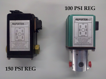 |
| Figure 1 — Regulator Styles |
|---|
- Finer - press the "1" button to toggle machine type between finer and polisher.
| Warning, toggling this control will require you to reset all of the material parameters! |
|---|
- FIN/POL - press the "2" button to toggle between Optek protocol (FIN/POL) for LensMate or Cnet Server and
3rd Party applications (DNL).
- Autostart - press the "3" button to toggle between ON and OFF.
- Regulator MAX Pressure setting - Set according to regulator installed in machine.
#4 Maintenance
The Maintenance Menu is used to access the timers (how long the machine has run), next maintenance due, and motor ramping time.
- Factory & User Timers - displays both the factory time (total running) and user time (time between user resets). User time is reset able.
- Next Maintenance Due - displays the next scheduled time or date for maintenance. When maintenance is required, the Criterion MAX will display a maintenance due screen. Once maintenance is performed the qualified maintenance person will enter their initials into the system to record completion.
| Description | Screen |
| Maintenance Menu Screen |  |
| Factory & User Timers Screen |  |
| Next Maintenance Due Screen |  |
| Start-Stop Delays Screen |  |
- Start-Stop Delays - displays the Auto Start Delay (time between clamp arms being lowered and cycle start - Autostart must be set to ON ), Unclamp Delay (time between cycle end and clamp arms being raised), the Blowoff Delay and Duration (how many seconds after the clamp arms retract and for how long the blowoff operates). The default settings in manual should not be changed unless advised by a Service Technician.
- Orbit/Stroke Pattern Check - used to verify that the orbit and stroke pattern are correct. See Chapter 6: Calibration for details.
Under certain infrequent circumstances (such as after replacing a major component) it may be necessary to make mechanical adjustments to the Criterion MAX's stroke or orbit. This chapter will help you become acquainted with the calibration process and guide you through the procedures.
The orbit is set independently for each drive unit on your Criterion MAX. When you check or adjust the orbit for one drive unit, you should do so for the other drive unit as well.
Recommended Orbit Settings
| Material | Cycle | Orbit |
|---|
| Plastic | Fine | 18mm |
| Polish | 18mm |
| Glass | Fine | 18mm |
| Polish | 20mm |
Items Needed
- 3/32" and 3/16" hex keys
- Grease or marking pen
- Metric ruler
- Setup block (4000-407) or the bottom half of the axis alignment block (4000-316)
|
Never perform any maintenance or adjustments without disconnecting the
equipment from utility power. Always wear eye protection while operating
or servicing equipment. |
Measuring the Orbit Diameter
- Unplug the Criterion MAX from utility power.
- Clamp the block onto the tool table.
- Color the top of the block with the marking pen or lightly coat it with grease.
- Open the cabinet door and locate the drive sheave on the bottom of the drive unit.
| If you are using the bottom half of the axis alignment block, add 2 mm to the measurement in step 7 to get the actual orbit. |
- Push the clamp arm down by hand until the tip of one of the axis pins is touching the top of the block.
- Hold the axis pin against the block while manually rotating the drive sheave. Continue to rotate the sheave until the tip of the axis pin scribes one complete circle.
- Measure the scribed circle diameter with the metric ruler.
- If the orbit diameter is not correct according to the chart, adjust as follows:
Changing the Orbit Diameter
| Read the entire section, Changing the Orbit Diameter, prior to completing steps 1 - 6. |
|---|
- Unplug the Criterion MAX from utility power.
- Locate the two #10-32 setscrews (4000-130) in the lower rim of the drive sheave on the bottom of the drive unit (4250-004).
| Loosening the setscrew near the "+" marking on the bearing plate (older plates have two tapped holes) will increase the orbit diameter. Loosening the other setscrew will decrease the orbit. |
|---|
- Use the 3/32" hex key to loosen the appropriate setscrew, one full turn is 1.6 mm of change in orbit diameter.
- Use the 3/16" hex key to loosen, but not remove, the three screws (4000-124) holding the bearing housing (4000-020) to the sheave.
- Tighten the setscrew opposite the one loosened in step 2 until the bearing housing is in contact with both setscrews. This will slide the bearing housing in the appropriate direction.
- Retighten the three screws loosened in step 3.
- Follow the instructions in the previous section to recheck the orbit diameter. If orbit is still not correct, repeat steps 1-6 unit correct orbit is achieved.
The traverse stroke is set independently for each drive unit on your Criterion MAX. When you check or adjust the traverse stroke for one drive unit, you should do so for the other drive unit as well. The Traverse stroke is adjusted until it is centered over the spindle centerline.
Items Needed
- 5/32" hex key
- 1/2" open-end wrench
- Grease or marking pen
- Setup block (4000-407) or the bottom half of the axis alignment block (4000-316)
- Clamp arm puller (4000-402)
Measuring the Stroke
| Step# | Description | Screen |
| #2 | Main Menu Screen | |
| #3 | Setup Menu |  |
| #4 | Maintenance Menu | |
| #5-8 | Orbit/Stroke Pattern Check Screen |  |
| #9 | Remove Hands Screen | |
| #10 | Running Screen |  |
| #11 | End of Cycle Unclamping Screen |  |
| Steps 1 - 11 requires that electrical power be supplied to the equipment systems while you are working. Please exercise extreme caution, paying special attention not to touch any moving parts with your hands or tools. Always wear eye protection while operating or servicing equipment. |
|---|
- Aim the slurry hose nozzles away from the tool tables and remove the suction cup from the clamp arm.
- On the Main Menu, press "3" to access the Setup Menu.
- Press "4" to access the Maintenance Menu.
- Press "4" to access the Pattern Check.
- Color the top of the block with the marking pen or lightly coat it with grease.
- Clamp the block onto the tool table.
- Remove hands from bowl.
- Press Enter ().
- Once the clamp arms have descended, the cycle will start (Autostart ON). If Autostart is set to OFF, press enter to begin cycle.
- The Criterion MAX will run for 1 minute at high speed.
- At the end of the 1 minute cycle, the clamp arms will retract and the controller will return to the Maintenance Menu.
| Disconnect power before proceeding. Never perform any maintenance or adjustments without disconnecting the equipment from utility power. Always wear eye protection while operating or servicing equipment. |
|---|
- Unplug the Criterion MAX from utility power.
- Label the left and front (toward operator) sides of the block while on the tool table.
- Remove the block and measure the distance between the edge of the pattern and the edge of the block on the left and right sides.
- If these measurements are the same, proceed to step 23.
Side to Side Adjustment
- Unlatch and open the hood.
- Use the 1/2" open-end wrench to loosen the lock nut (4000-181) against the rod end (4000-179) connected to the traverse (4000-018).
- Use the 1/2" open-end wrench to remove the bolt (8000-355) securing the rod end to the bottom of the traverse.
| Example: if the left spindle measurements are 2 mm on the left side of the block and 6 mm right side, the rod end needs two full turns clockwise. This will yield a 4 mm measurement on each side. |
- Screw the rod end in (clockwise) to move the traverse stroke toward the centerline of the Criterion MAX. Screw the rod end out (counterclockwise) to move the traverse stroke away from the centerline of the Criterion MAX. One full turn on the rod end will add 1 mm to one side and subtract 1 mm from the opposite side.
- Use the 1/2" open-end wrench to install the bolt securing the rod end to the bottom of the traverse.
- Use the 1/2" open-end wrench to tighten the lock nut against the rod end connected to the traverse.
| Make sure that the flat faces of the rod end pairs remain parallel to each other. This will prevent the rod ends from binding when the clamp arms are in the fully up and down positions. |
|---|
- Close and latch the hood.
| If you are using the axis alignment block, the rear measurement should be 1.5 mm less than the front measurement. |
Front to Back Adjustment
- Measure the distance between the edge of the pattern and the edge of the block on the front (toward operator) and rear sides.
- If these measurements are the same, skip steps 25-27.
- Use the 5/32" hex key to loosen the setscrew (4000-158) on the bottom of the clamp arm (4000-108).
| Example: if the front measurement is 15 mm and the rear measurement is 10 mm, the clamp arm should be moved 2.5 mm toward the front. |
- Move the clamp arm toward or away from the operator one-half of the measured difference. A clamp arm puller (4000-402) may be required.
- Retighten the setscrew.
Adjusting the Clamp Arm Height
After replacing the clamp arm air cylinder or rod ends, you may need to adjust the distance between the tip of the tool pins and the lap table. If this distance is not correct you may be unable to load blocked lenses or lenses may not be clamped securely.
Items Needed
- 1/2" box end wrench
- Metric ruler
|
Never perform any maintenance or adjustments without disconnecting the
equipment from utility power. Always wear eye protection while operating
or servicing equipment. |
Procedure
- Unplug the Criterion MAX from utility power.
- Follow the instructions on under Timing and Tensioning the Breakup and High Speed Sheaves and Belts to remove the belts from the drive unit.
- Rotate the breakup (upper) sheave on each drive unit until the stamped "2" is aligned with the lube fitting above it.
- Rotate the high speed (lower) sheave on each drive unit until the stamped "X" is facing the back of the machine (the set screw in the lower sheave without the "X" above it will line up with the lube fitting.)
- Use the 1/2" box end wrench to loosen the jam nut on the bottom rod end of the air cylinder.
- Remove the nut and the bolt from the bottom rod end.
- Rotate the clamp arm so that it is level.
- Use the metric ruler to measure the distance between the tip of one tool pin and the top of the tool table.
- If the distance is not 60 mm, turn the bottom rod end to adjust as needed. Turn the rod end clockwise/counterclockwise (as seen from the bottom of the cylinder) to increase/decrease the distance.
- Reinstall the bolt and the nut at the bottom of the air cylinder and tighten securely.
- Tighten the jam nut on the rod end.
- Check that the airlines attaching to the air cylinder do not rub.
- Follow the instructions under Timing and Tensioning the Breakup and High Speed Sheaves and Belts to retime drive units.
| Failure to perform these simple procedures may lead to expensive damage to the machine! |
Maintenance of your Optek Criterion MAX Surfacer is extremely simple. Nevertheless, it is essential for optimal results. This section lists all of the maintenance procedures that operators may be expected to perform.
|
Never perform any maintenance or adjustments without disconnecting the
equipment from utility power. Always wear eye protection while operating
or servicing equipment. |
Lubrication
Your Criterion MAX has been designed for extended periods of use between lubrication sessions. Proper lubrication, however, cannot be ignored without serious, long-range detriment to machinery life and reliability.
Approved Lubricants
Optek has done long-term testing with many different lubricants. We recommend the use of premium products. The use of common automotive greases in place of the recommended products can result in a sixty-percent decrease in bearing life.
| The savings gained from purchasing inexpensive grease is trivial compared to the cost of replacing a drive unit. Bargain lubricants are no bargain |
|---|
| Approved Lubricant | Optek Part Number | Where Used |
|---|
| Lubriplate MAG-1 grease | 8200-341 | Drive unit, spindle bearing |
| Lubriplate 3V SAE 20 machine oil | 7000-130 | Traverse, clamp assembly, gimbal assembly |
| Dem-kote silicone spray | 7000-223 | General maintenance |
| Fel-pro C5-A anti-seize compound (or equivalent) | Available locally | General maintenance
|
| Liquid Wrench (or equivalent) | Available locally | General maintenance |
Lubrication Schedule
Following the recommended lubrication schedule is extremely important in helping you achieve the reliability and longevity that your Criterion MAX is designed to provide. The Criterion MAX's control will automatically advise you to when each service interval is reached.
|
Never perform any maintenance or adjustments without disconnecting the
equipment from utility power. Always wear eye protection while operating
or servicing equipment. |
| Lubrication Point | On Screen Description | Interval | Lubricant | Description |
|---|
| Air tool table clamp | N/A | Weekly | Silicone lubricant (5000-033), R.B. grease | See Cleaning the Air Tool Tables under Maintenance Procedures. |
| Secondary and Traverse Baffles | N/A | Weekly | Dem-kote silicone spray | See Weekly Maintenance. |
| Spindle bearings (4000-129) | Monthly | 200 hours of operation | Lubriplate MAG-1 grease | Locate the two grease fittings on the underside of the bottom sheave and apply one-half pump to each with the unit off. |
| Traverse (4000-018) assembly | Monthly | 200 hours of operation | Lubriplate 3V SAE 20 machine oil | Fill the one oil detent and two oil cups on the top. |
| Gimbal assemblies (4000-086) | Monthly | 200 hours of operation | Lubriplate 3V SAE 20 machine oil | Fill the three oil detents on the front. |
| Lubricating the drive unit requires that electrical power be supplied to the equipment systems and the machine running while you are working. Please exercise extreme caution, paying special attention not to touch any moving parts with your hands or tools. Always wear eye protection while operating or servicing equipment. |
|---|
| Lubrication Point | On Screen Description | Interval | Lubricant | Description |
|---|
| Drive unit (4250-004) | Drive Units | 100 hours of operation | Lubriplate MAG-1 grease | Locate the single grease fitting reached through the front panel below the bowl. Apply one pump of grease while the unit is running. |
Daily Maintenance
These procedures should be performed at least once each day.
|
Never perform any maintenance or adjustments without disconnecting the
equipment from utility power. Always wear eye protection while operating
or servicing equipment. |
- Inspect all belts for obvious wear.
- Clean the secondary and traverse baffles with fresh water. If polish is to be left in the bowl overnight, rinse the baffles and tool table clamps with a spray bottle.
- Inspect all baffles for abrasions or cuts and replace as necessary.
- Drain the surfacer, flush the pump with clean fresh water, and wipe dry.
- Drain water from airline filter.
Weekly Maintenance
These procedures should be performed at least once a week.
|
Never perform any maintenance or adjustments without disconnecting the
equipment from utility power. Always wear eye protection while operating
or servicing equipment. |
- Rinse the secondary and traverse baffles with fresh water, dry them, and treat them with silicone spray (7000-223).
- Clean tool tables by follow the procedure in "Cleaning Air Tool Tables."
- Check Tool Table for excessive side to side and front to back play. See Adjusting the Gimbal Thrust Bearings if adjustment is necessary.
- Check Clamp Arm for excessive front to back play. See Adjusting and Cleaning the Traverse Thrust Bearings if adjustment is necessary.
- Check Tool Pins for excessive wear. See Replacing the Axis Pins if replacement is necessary.
Maintenance Procedures
The tool table clamp will become contaminated with slurry and difficult to move. Disassembly and cleaning will be necessary.
Items Needed
- Silicone Lubricant (5000-033)
- R.B. grease
- Toothbrush
- Toothpick
- 5/32" Allen Wrench
- 3/16" Allen Wrench
- Dry cloth
|
Never perform any maintenance or adjustments without disconnecting the
equipment from utility power. Always wear eye protection while operating
or servicing equipment. |
Procedure
- Unplug the Criterion MAX from utility power and air supply.
- Use the 3/16" Allen wrench to remove the four socket head cap screws (4250-106) that mount the air cylinder body to the lap table. This will allow for the removal of the front clamp.
- Pull the two small springs (4000-164) out of their holes in the front of the tool table.
- Using the 5/32" Allen wrench, remove the four socket head cap screws (4250-179) that hold the end cap (4250-168) on to the air cylinder body (4250-171).
- Remove the gasket (4250-172) and piston from the air cylinder body.
- Scrub all parts, including the shaft and tool table. Do not forget to clean out the two spring holes. A toothpick is handy for removing accumulated polish from small holes. Rinse all parts with clean water and dry.
- Apply silicone lube to the "O" ring located inside the air cylinder body along with the "O" ring on the piston.
- Carefully, reinstall the piston into the air cylinder body.
- Replace the gasket (4250-172), end cap (4250-168) and four socket head cap screws (4250-179).
- Pack the spring holes in the tool table with R.B. grease to prevent polish from binding the springs.
- Replace the two springs and the front clamp. Make sure that the milled groove on the jaw is up and facing toward the tool table.
- Position the air cylinder assembly in its correct location and replace the four socket head cap screws (4250-106).
- Using the foot pedal, cycle the tool table to see if it is clamping properly.
Axis pins (4000-103) become worn over time and must be replaced to ensure proper axis control. Always replace all four axis pins at the same time.
Items Needed
- 1/8" pin punch
- 5/32" hex key
- Anti-seize compound
- Axis alignment block (4000-316)-lower half only
- (4) New axis pins (4000-103 sharp, or 4000-198 blunt)
- Penetrating oil (such as Liquid Wrench)
|
Never perform any maintenance or adjustments without disconnecting the
equipment from utility power. Always wear eye protection while operating
or servicing equipment. |
Procedure
- Unplug the Criterion MAX from utility power.
- Remove the suction cup and barb fitting from the clamp arm.
- Open the cabinet door.
- Manually rotate the lower sheave on the drive unit counterclockwise to center the tool table assembly directly under the clamp arm.
- Close the cabinet door.
| Steps 6 - 16 requires that electrical power be supplied to the equipment systems while you are working. Please exercise extreme caution, paying special attention not to touch any moving parts with your hands or tools. Always wear eye protection while operating or servicing equipment. |
|---|
- Plug the Criterion MAX into the utility power and turn on machine
- Place the alignment block on the tool table on its long edge. Slide it back against the rear jaw.
- Push the clamp arm down against the block
- At the Main Menu, press "4" to access the Pump/Clamp Menu.
- Press "F2" to activate the clamp arms in the down position.
 |
| Figure 2 — Axis Pins |
|---|
- While holding the clamp arm to prevent turning, use the 5/32" hex key to loosen the two cap screws (4000-152) in the front of the pin holder assembly.
- Drive the old axis pins out using the 1/8" pin punch.
- Lightly coat the new axis pin shanks with the anti-seize compound.
- Install the new axis pins and firmly tighten the two cap screws while holding the clamp arm.
- Press "F2" to release the clamp arm.
- Remove the alignment block.
- Repeat steps 1-13 for the other spindle.
- Follow the procedure in "Adjusting the Axis Alignment."
Always check the axis alignment if the axis pins or pin holders have been removed or if the tool table has been disturbed or removed.
Items Needed
- 1/2" wrench
- Axis alignment block (4000-316)
|
Never perform any maintenance or adjustments without disconnecting the
equipment from utility power. Always wear eye protection while operating
or servicing equipment. |
Procedure
- Unplug the Criterion MAX from utility power.
- Clamp the lower half of the axis alignment block onto the tool table with the grooved side down.
- Place the upper half of the axis alignment block on top of the lower half.
- With your hand, push the clamp arm down and position the axis pins in the groove on the alignment block.
- Open the cabinet door.
- Rotate the lower sheave of the drive unit, by hand, until the front edges of the alignment block halves are aligned as closely as they can be. If the edges align satisfactorily, proceed to step 9.
- Use the 1/2" wrench to loosen the screw securing the pin holder assembly.
- Rotate the pin holder assembly until the front edges of the alignment block halves are aligned. Retighten the screw, being careful not to rotate the pin holder assembly.
- Unclamp and remove the alignment block from the tool table.
Grasp each tool table and attempt to wiggle it front-to-back and side-to-side. If there is any play, you must check and, if necessary, adjust the thrust bearings.
| Apparent gimbal play may also be caused by worn spherical spindle bearings. |
If adjusting the gimbal thrust bearings does not eliminate the play, the gimbal assembly should be replaced. See the Gimbal Assembly Replacement section of chapter 9.
Items Needed
|
Never perform any maintenance or adjustments without disconnecting the
equipment from utility power. Always wear eye protection while operating
or servicing equipment. |
Procedure
- Unplug the Criterion MAX from utility power.
- Open the cabinet door and remove the front access panel above it.
- Locate the three gimbal thrust collars — silver metal washers, one directly behind each adjusting nut.
- Rotate each thrust collar by hand. You should feel a firm resistance if they are properly adjusted.
- If the thrust collars need adjustment (always adjust the cross shaft collars first):
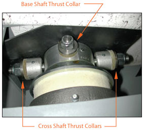 |
| Figure 3 — Gimbal Thrust Adjustments |
|---|
- Use the 15/16" open end wrench to adjust the cross shaft collar nut toward the center of the surfacer until the cross shaft collars turn with firm resistance. (Tightening this one nut adjusts both cross shaft collars.)
- Use the 3/4" open end wrench to adjust the base shaft collar nut until the base shaft collar turns with firm resistance.
| Never tighten an adjusting nut to the point that you cannot turn the thrust collar by hand. Doing so may damage the thrust bearing and cause premature wear. |
|---|
- Replace the front access panel and close the cabinet door.
After the first forty to eighty hours of operation, the traverse thrust bearings should be checked for looseness (front-to-back). Thereafter, the traverse thrust bearings should be periodically rechecked.
If the clamp arm does not swivel freely, then the thrust bearings have become contaminated. They must be disassembled, cleaned, lubricated, and adjusted.
Items Needed
- 5/32" hex key
- Fine file
- Rag
- Lubriplate MAG-1 grease (8200-341)-if cleaning the thrust bearings
|
Never perform any maintenance or adjustments without disconnecting the
equipment from utility power. Always wear eye protection while operating
or servicing equipment. |
Procedure
- Unplug the Criterion MAX from utility power.
- Remove top lid.
- Unlatch and open the hood.
- Use the 5/16" hex key to loosen the setscrew (4000-150) in the collar on the rear end of the traverse assembly (4000-018) and slide the collar off.
- Use the fine file to remove the burr raised by the setscrew in the slot on the clamp shaft.
- Use the rag to wipe any filings from the clamp shaft, making sure that the filings do not get into the thrust washers or fall into the machine.
- Slide the rear collar on the shaft. Be sure the setscrew in the front collar is positioned on top, between the two travel limit pins.
- While applying pressure to the front of the clamp shaft, hold the rear collar against the thrust washer and tighten the setscrew. The angled face on the clamp shaft will draw the collar in to the proper preload.
All belts must be retensioned from time to time. A belt should be replaced whenever it begins to show signs of excessive wear. The Optek timing belt system allows the Criterion MAX to operate with a minimal amount of vibration. In order to preserve this feature, drive unit timing must be adjusted each time a belt, old or new, is installed.
Items Needed
- 5/16" hex key
- (2) Timing belts (4250-054)-if replacement is required
- Straight Blade screwdriver
- Belt Path Drawing - click link to display
|
Never perform any maintenance or adjustments without disconnecting the
equipment from utility power. Always wear eye protection while operating
or servicing equipment. |
Procedure
Belt Identification
- The High-Speed and Breakup timing belts are the same size-part number (4250-054).
- The lower of the two belts is known as the High-Speed belt, while the upper is the Breakup belt.
Belt Removal
- Unplug the Criterion MAX from utility power.
- Use the hex key to loosen the screw (8000-824) holding each of the belt-tightener idler assemblies.
- The plain-roller idler assembly (4250-050) for the lower belt is between the drive units.
- The gear sheave idler assembly (4250-021) for the upper belt is behind and slightly to the left of the right-hand drive unit.
- Remove both belts.
- If either belt shows indications of excessive wear or stretching, discard both belts and replace.
Timing (Breakup Sheave)
- Rotate the breakup (upper) sheave on each drive unit until the stamped "1" is aligned with the lube fitting above it.
- Rotate the right-hand breakup sheave seven notches toward the left.
- Install the breakup belt, taking care not to move the sheaves.
Tensioning (Breakup Belt)
- Push the gear sheave of the belt tightener assembly (4250-021) toward the rear to increase the belt tension until snug. Use the 5/16" hex key to retighten the screw (8000-824).
Timing (High-Speed Sheave)
- Rotate the left-hand high-speed (lower) sheave until the "X" points straight toward the front of the unit.
- Rotate the right-hand high-speed sheave until the "X" points straight toward the back of the unit.
- Install the high-speed timing belt, taking care not to move the sheaves. Ensure that it passes around the spring-loaded idler sheave (4250-040) on the left side of the cabinet.
| The gear belts do not need to be very tight to function properly. Over tightening will cause premature belt failure. |
Tensioning (High-Speed Belt)
- Pull the plain roller of the belt tightener assembly (4250-050) toward the front to increase the belt tension. Retighten the screw.
Verify Correct Belt Timing
| Verifying the belt timing requires that electrical power be supplied to the equipment systems and the machine running while you are working. Please exercise extreme caution, paying special attention not to touch any moving parts with your hands or tools. Always wear eye protection while operating or servicing equipment. |
|---|
- Using a straight blade screwdriver, release the four 1/4 turn screws holding the lid to the hood.
- Remove lid.
- Without a lens and lap in place, start the machine and observe the following:
- Observe the Spring Loaded Belt Tightener (4250-054) for excessive movement. This movement should be 1/2" or less. If this movement is greater than 1/2", it will be necessary to repeat the Timing and Tensioning of the High Speed Sheave and Belt
- Operation should be smooth with no noise or banging. If machine is making a noise, it will be necessary to repeat the Timing and Tensioning of the Breakup Sheave and Belt.
Jackshaft/Gear Reducer Belt
Items Needed
- 9/16" wrench
- Timing belt (4250-464)-if replacing the belt
|
Never perform any maintenance or adjustments without disconnecting the
equipment from utility power. Always wear eye protection while operating
or servicing equipment. |
Procedure
- Unplug the Criterion MAX from utility power.
- Use the 9/16" wrench to loosen the three screws (8000-354) on the front of the mounting plate (4250-039).
- Slide the jackshaft assembly (4250-011) outward to increase the tension on the belt.
- Retighten the three screws.
Primary Motor/Jackshaft Belt
- 7/16" wrench
- Timing belt (4250-055)-if replacing the belt
|
Never perform any maintenance or adjustments without disconnecting the
equipment from utility power. Always wear eye protection while operating
or servicing equipment. |
Procedure
- Unplug the Criterion MAX from utility power.
- Locate the drive motor adjusting screw, positioned to the far left of the motor.
- Loosen the nut (2000-019) on the front of the motor mounting plate using the 7/16" wrench.
- Use the 7/16" wrench to adjust the nut (2000-019) on the rear of the motor mounting plate. Adjust the nut forward on the carriage bolt (4250-163) to decrease belt tension, rearward to increase it.
- Retighten the front nut to lock the assembly.
Gear Reducer/Eccentric Drive Pulley Belt
- 5/16" hex key
- Timing belt (4250-070)-if replacing the belt
|
Never perform any maintenance or adjustments without disconnecting the
equipment from utility power. Always wear eye protection while operating
or servicing equipment. |
Procedure
- Unplug the Criterion MAX from utility power.
- Loosen the screw (8000-201) securing the belt tightener assembly (4250-079) using the 5/16" hex key. This tightener assembly is located between the jackshaft and the gear reducer.
- Pivot the belt tightener toward the left to increase tension on the belt.
- Retighten the screw.
Pump Drive Belt (glass machines only)
- Adjustable wrench
- Timing belt (4500-035)-if replacing the belt
|
Never perform any maintenance or adjustments without disconnecting the
equipment from utility power. Always wear eye protection while operating
or servicing equipment. |
Procedure
- Unplug the Criterion MAX from utility power.
- Loosen the nut holding the motor to the motor mount.
- Pivot the motor counterclockwise to tighten the belt.
- Retighten the nut.
In normal operation the tool tables may need replacement. This section details the procedure.
Items Needed
- 1/8" hex key
- 1/4" wrench or nut driver
- 5/16" hex key
- Fine file
- Penetrating oil (such as Liquid Wrench)
- Tool table puller (4000-313)
|
Never perform any maintenance or adjustments without disconnecting the
equipment from utility power. Always wear eye protection while operating
or servicing equipment. |
Procedure
- Unplug the Criterion MAX Surfacer from utility power.
- Use the 5/16" hex key to remove the locator screw (4000-057) and the copper spacer (4000-502) from the top of the tool table (4000-034, 4000-085).
- Use the 1/4" wrench or nut driver to remove the six screws (4000-161) holding the baffle (4250-072) and flange (4250-073) to the bowl.
- Fill the locator screw hole with penetrating oil and allow it to soak.
- Use the 1/8" hex key to loosen the two setscrews (2000-029) located in the sides of the tool table.
| If the setscrew holes (step 4) have not been kept filled with grease as recommended, the screws may be difficult or impossible to remove. If they cannot be removed, the spindle shaft may be slightly marred during this procedure, but will not have to be replaced. |
|---|
- Open the cabinet door and rotate the drive unit by hand until the tool table is closest to the front of the bowl. Close the door.
- Insert the screw (8000-205) provided with the tool table puller into the locator screw hole, and screw it in at least five full turns.
 |
| Figure 4 — Tool Table Puller |
|---|
- Place the tool table puller over the tool table and insert the puller's side pins into the holes on either side of the table. You may need to clean the holes before the pins will go in.
- Turn the tool table puller handle until the tip of the puller shaft enters the hole in the top of the screw.
- Continue turning until the tool table is loose on the spindle shaft.
| You may need to heat the tool table with a propane torch or heat gun while tightening the tool table puller. If the tool table must be heated for removal, allow it to cool before touching it. |
|---|
- Remove the tool table puller and its screw.
- Lift off the tool table and secondary baffle (4000-072). The two pressure washers (4250-115) may fall out. Save them for reuse.
- Check the primary and secondary baffles while the tool table is off. If replacement is necessary see Secondary Baffle Replacement or Primary Baffle Replacement.
- Clean the exposed portion of the gimbal shaft. Use a fine file to remove any burrs, especially any caused by removing the table with the setscrews still tight.
- Clean off the silicone sealant around the screw holes in the bowl.
Cuts or punctures of the secondary spindle baffles will allow slurry to penetrate up to the primary baffle. Since it is impossible to be assured of the integrity of the primary baffle without removing the tool table, a damaged secondary baffle should always be replaced.
| Damaged baffles should always be replaced as soon as possible. |
|---|
Items Needed
- 5/16" wrench or nut driver
- Abrasive disk (4000-116)
- Flat-bladed screwdriver
- Secondary baffle (4250-072)
- 1/4" wrench or nut driver
- Silicone sealant
- Baffle Drawing - click link to display
|
Never perform any maintenance or adjustments without disconnecting the
equipment from utility power. Always wear eye protection while operating
or servicing equipment. |
Procedure
- Unplug the Criterion MAX Surfacer from utility power.
- Follow the procedure detailed in "Tool Table Removal".
- Remove the four screws (4250-088) and nuts (4250-087) clamping the secondary baffle (4250-072) between the baffle shield (4250-074) and the baffle ring (4250-086) using the 5/16" wrench or nut driver and the screwdriver.
- Remove and discard the old secondary baffle and the two abrasive disks.
- Inspect the primary baffle (4000-115) for cuts, punctures, or wear. Replace if necessary, following the procedure detailed in "Primary Spindle Baffle Replacement".
- Inspect the tool table and its components for excessive wear. Replace if necessary.
- Apply a small amount of the Silicone sealant to the bottom of the baffle shield (4250-074M) around the center hole. This ensures that the abrasive disk does not shift during assembly.
- Install a new abrasive disk (4000-116) to the center of the baffle shield. The notch in the disc must face the front of the tool table. The rough side must face down (away from the tool table).
- Apply a small amount of Silicone sealant to the bottom of the baffle shield where the baffle ring will contact.
- Assemble the secondary baffle and the baffle ring to the baffle shield.
- Insert the four screws from inside the secondary baffle and the four nuts on top of the shield. The tall side of the baffle faces the front (clamp handle side) of the tool table.
- Follow the procedure detailed in "Tool Table Replacement".
Cuts or punctures of the primary spindle baffles will allow slurry to penetrate into the interior of the machine. While slurry cannot drip directly onto the moving parts, it can overflow into the machine, greatly accelerating wear.
Items Needed
- Abrasive disk (4000-116)
- Primary baffle (4000-115)
- Vinyl sealing tape (4000-117)
- Baffle Drawing - click link to display
|
Never perform any maintenance or adjustments without disconnecting the
equipment from utility power. Always wear eye protection while operating
or servicing equipment. |
Procedure
- Unplug the Criterion MAX Surfacer from utility power.
- Remove the tool table and secondary baffle as detailed in this chapter.
- Remove the old vinyl sealing tape holding the primary baffle to the neck of the bowl.
- Remove and discard the old primary baffle and the old abrasive disks.
- Clean the neck of the bowl, being careful to remove all traces of the old sealing tape and adhesive.
- Place the new abrasive disk over the spindle neck and under the locating pin. The rough side must face up.
- Place the new primary baffle over the spindle neck and under the locating pin.
- Use both hands to pull the bottom of the primary baffle over the bowl neck. Be sure the baffle is positioned evenly around the neck and approximately 3/8" above the bowl floor in the front.
- Rotate the spindle by hand and observe the motion of the primary baffle.
- Adjust the height of the bottom of the baffle on the bowl neck, if necessary, until the baffle moves smoothly, with no puckering or pulling.
| Any irregularity in the flexing motion strains the baffle and causes premature failure. |
|---|
- Use the new sealing tape to secure the lower edge of the baffle to the bowl neck. Do not allow the baffle to slip during this operation. The tape must seal to both the baffle and the bowl neck all the way around.
| Do not apply the tape above the point where the baffle begins to flex, as this will cause strain and premature failure. |
|---|
- Rotate the spindle by hand and check the motion again. If not satisfactory, remove the sealing tape and repeat steps 9-11.
- Reassemble the secondary baffle and tool table to the spindle as described in this chapter.
Items Needed
- 1/8" hex key
- 1/4" wrench or nut driver
- 5/16" hex key
- Abrasive disk (4000-116)
- Copper spacer (4000-502)
- Anti-seize lubricant
- R.B. grease
- Silicone sealant
- Tool Table Assembly Drawing - click link to display
|
Never perform any maintenance or adjustments without disconnecting the
equipment from utility power. Always wear eye protection while operating
or servicing equipment. |
Procedure
- Unplug the Criterion MAX Surfacer from utility power.
- Apply a liberal bead of the silicone sealant to the bottom of the flange of the secondary baffle (4250-073). Install the baffle flange to the baffle insuring that the "T" is facing up and the six holes are aligned to the holes in the baffle. Allow at least one hour for the silicone to dry before proceeding with step 6.
- Lightly coat the two 1/4" setscrews (2000-029) with the anti-seize compound.
- Install the setscrews and the two pressure washers (4250-115) in the holes in the sides of the tool table. (Note: 4000-034M includes set screws and pressure washers installed loosely.)
- Coat the neck of the gimbal shaft (4000-045) with the anti-seize compound and place the tool table assembly onto the gimbal shaft.
- Apply a small bead of silicone adhesive to the bottom side of the baffle below the baffle flange on the rubber that will contact the sink.
- Place the new abrasive disk over the spindle neck and on top of the primary baffle. The rough side must face up.
- Install the tool table/baffle assembly on to the spindle shaft.
- Carefully replace the six screws (4000-161) using the 1/4" wrench or nut driver. Do not over tighten.
- Install the copper spacer (4000-502) and the locator screw (4000-057) using the 5/16" hex key. Tighten until the tool table is firmly seated onto the spindle neck.
| Failure to install the copper spacer (4000-502) will result in slurry leaks and corrosion of the machine's internal components. |
|---|
- Use the 1/8" hex key to tighten the two setscrews in the sides of the tool table.
- Fill the setscrew holes with R.B. grease.
- Set the axis alignment following the procedure detailed in the "Adjusting Axis Alignment" section of Chapter 6.
- Set the orbit following the procedure detailed under "Orbit" in section of Chapter 5 Calibration.
Traverse Baffle Replacement
Cuts or punctures of the traverse baffles will allow slurry to splash onto the front traverse thrust bearing seal. The slurry may then migrate into the thrust bearing and the bronze bearings.
Items Needed
- 5/32" hex key
- 1/4" wrench or nut driver
- Clamp arm puller (4000-402)
- Silicone lubricant (5000-033)
- Traverse baffle (4000-075)
|
Never perform any maintenance or adjustments without disconnecting the
equipment from utility power. Always wear eye protection while operating
or servicing equipment. |
Procedure
- Unplug the Criterion MAX Surfacer from utility power.
- Use the 5/32" hex key to remove the setscrew (4000-158) on the bottom of the clamp arm.
- Remove the clamp arm using the clamp arm puller.
- Remove the retaining ring (4000-288).
- Use the 1/4" wrench or nut driver to remove the six screws (4000-161) from the baffle flange (4000-73).
- Remove the baffle flange and the traverse baffle.
- Apply silicone lubricant (5000-033) to the inside of the new traverse baffle neck.
- Install the new traverse baffle, baffle flange, and six screws.
- Place the retaining ring onto the traverse shaft.
- Install the clamp arm.
- Reinstall the setscrew into the bottom of the clamp arm and tighten.
- Set the axis alignment following the "Adjusting the Axis Alignment" procedure in Chapter 6.
- Set the stroke following the "Traverse Stroke Adjustment" procedure in Chapter 5.
| The spindle bearing and spindle shaft should always be replaced at the same time. Only use snap rings purchased from Optek. |
|---|
Items Needed
- 3/32" and 3/16" hex keys
- 3/8" wrench
- 7/16" six-point socket
- Set of 3/8" or 1/2" drive sockets
- Lubriplate MAG-1 grease (8200-341)
- Ball-peen hammer
- Snap ring pliers
- Spindle bearing (4000-129)
- Spindle shaft (4000-119)
- Snap Ring (4000-128)
|
Never perform any maintenance or adjustments without disconnecting the
equipment from utility power. Always wear eye protection while operating
or servicing equipment. |
Procedure
- Unplug the Criterion MAX Surfacer from utility power.
| Make a mark on the rim of each sheave to indicate which setscrew was loosened in step 3. Retighten this same screw in step 14. |
- Use the 3/8" wrench to remove the grease fitting from each bearing housing.
- Use the 3/16" hex key to remove the three screws (4000-124) and washers (4000-125) that hold the bearing housing to the drive unit.
- Support the bearing housing while using the 3/32" hex key to loosen one of the setscrews (4000-130) in the rim of the lower sheave. Remove the bearing housing.
- Use the 7/16" six-point socket to remove the spindle shaft (4000-119).
- Use the snap ring pliers to remove the snap ring (4000-128) from the bearing housing.
- Turn the bearing housing over so that the grease fitting holes are facing down. From the set of sockets, find the largest that will fit into the bearing hole.
- Use the hammer and socket to drive out the old spindle bearing.
- Turn the bearing housing over. Ensure that the bore and shoulder are free of any foreign matter that could cause misalignment of the new bearing.
- Find another, larger, socket that will just fit in the hole on this side of the housing.
- Align the spindle bearing over the hole with the edge that is notched facing up.
- Rotate the spindle bearing until the lubrication hole in the side of the bearing is inline with the lubrication hole in the bearing plate.
- Use the socket to carefully press in the new spindle bearing. Pressure must be applied only to the outer race of the bearing, and the bearing must remain straight.
- Insert new snap ring.
- Use the 7/16" six-point socket to screw the new spindle shaft into the gimbal spindle shaft and tighten securely.
- Reuse the three screws and washers to secure the bearing housing to the drive sheave. Finger-tighten the screws.
- Retighten the setscrews loosened in step 3.
- Finish tightening the three screws left loose in step 16.
- Replace the grease fittings.
- Set the orbit following the "Orbit" procedure in Chapter 5
This chapter identifies some of the major repairs that may become necessary after long-term service. The various sections will help you become acquainted with the general indications and guide you through the steps necessary to perform each repair. Careful attention to regular maintenance as instructed in previous chapters can have a dramatic effect on reducing the frequency and cost of major repairs.
Basic Tools
Each of these repairs will require basic mechanic's tools that should be purchased locally. All screws and bolts used in the Criterion MAX are inch (English/SAE) measurement system.
The tools needed will include:
- Screwdrivers of various sizes, both flat-bladed and Phillips
- A set of open-end wrenches
- A set of hex keys
- A socket driver and a set of sockets
Main Units
Major components, such as drive units, cannot be successfully rebuilt in the field. The reason for this is simple: The major components of your Criterion MAX are manufactured to extremely tight tolerances. This is one of the key features that allows Optek surfacers to provide the years of reliability and performance you have come to expect. Achieving this degree of precision, whether in the original manufacturing process or during a rebuild, requires expensive, specialized equipment.
Traverse Assembly Replacement
Symptoms of a failing traverse assembly typically present themselves as optical problems in your lenses. To determine if a traverse assembly needs to be replaced, lift the clamp arm as high as it will go. Holding the clamp arm in this position, attempt to wiggle it side-to-side. If you notice any play, the traverse assembly should be replaced.
Items Needed
- Anti-seize compound
- Clamp arm puller (4000-402)
- Traverse assembly (4000-018)
|
Never perform any maintenance or adjustments without disconnecting the
equipment from utility power. Always wear eye protection while operating
or servicing equipment. |
Procedure
- Unplug the Criterion MAX Surfacer from utility power.
- Remove the bolt (4000-289) connecting the traverse rod end to the bottom of the traverse.
- Remove the bolt (4000-289) and nut (4000-186) connecting the air cylinder rod end (4000-179) to the two air cylinder clevis brackets.
- Remove the setscrew (4000-158) on the bottom of the clamp arm (4000-108).
- Remove the airline from the clamp arm.
- Remove the clamp arm using the clamp arm puller.
- Remove the retaining ring (4000-288).
| In the next step, be sure to support the traverse assembly when removing the bolts. |
|---|
- Remove the two bolts (4000-209) holding the traverse assembly to the main mounting plate.
- Carefully slide the clamp shaft (4000-029) out of the traverse baffle (4000-075) and remove the old traverse assembly.
- Slide the new traverse assembly into place and reuse the two bolts (4000-209) to secure it.
- Install the retaining ring.
- Install the clamp arm and setscrew.
- Reuse the nut and bolt from step 2 to reattach the rod end to the clevis brackets.
- Reconnect the traverse rod end to the bottom of the traverse with the bolt from step 1. Make sure that the rod ends will not bind when the clamp arm is in the up or down position.
- Set the axis alignment following the "Adjusting the Axis Alignment" procedure in Chapter 6.
- Set the stroke following the "Traverse Stroke Adjustment" procedure in Chapter 5.
A failing drive unit will usually start with a slow or labored motion. It is even possible for it to seize completely. Similar symptoms, however, may result from over-greasing the drive unit, over-tightening the drive belts, a worn gimbal assembly, or starting the Criterion MAX at a very cold temperature. To determine if a drive unit assembly needs to be replaced, with the Criterion MAX unplugged from the utility power, open the cabinet door and attempt to wiggle the breakup sheave front-to-back and side-to-side. If you notice any play, the drive unit assembly should be replaced.
Items Needed
- Drive Unit assembly (4250-004)
|
Never perform any maintenance or adjustments without disconnecting the
equipment from utility power. Always wear eye protection while operating
or servicing equipment. |
Procedure
- Unplug the Criterion MAX Surfacer from utility power.
- Remove the spindle bearing housing following the "Spindle Bearing and Spindle Shaft Replacement" procedure in chapter 7.
- Remove the two timing belts from the drive units.
| Steps 4-6 require the aid of an assistant. The Drive Unit is heavy! When moving or lifting, please wear appropriate supports and exercise due caution to avoid personal injury or dropping and damaging the Drive Unit. |
|---|
- Remove the two bolts (4000-208) and lock washers (4000-199) from the main mounting plate.
- Remove the old drive unit assembly.
- Use the two bolts and lock washers to install the new drive unit assembly.
- Reinstall the spindle bearing housing following the "Spindle Bearing and Spindle Shaft Replacement" procedure in chapter 7.
- Replace the belts and time the drive units following the "Timing and Tensioning the Breakup and High-Speed Drive Sheaves and Belts procedure" in chapter 5.
- Set the orbit using the "Orbit" procedure in chapter 5.
Symptoms of a failing gimbal assembly typically present themselves as optical problems in your lenses. To determine if a gimbal assembly needs to be replaced, attempt to wiggle the tool table front-to-back and side-to-side. If you notice any play, first adjust the Gimbal Thrust bearings then inspect the spherical bearing and spindle shaft for wear. If excessive play still exists, the gimbal assembly should be replaced.
Items Needed
- Gimbal assembly (4000-086)
|
Never perform any maintenance or adjustments without disconnecting the
equipment from utility power. Always wear eye protection while operating
or servicing equipment. |
Procedure
- Unplug the Criterion MAX Surfacer from utility power.
- Remove the tool table and the secondary and primary baffles following the "Tool Table Removal" procedure detailed in chapter 7.
- Remove the drive unit assembly as following the "Drive Unit Assembly Replacement" procedure.
- Remove the four bolts (4000-208) and lock washers (4000-199) from the main mounting plate.
- Remove the old gimbal assembly.
- Reuse the four bolts and washers to install the new gimbal assembly.
- Replace the drive unit following the "Drive Unit Assembly Replacement" procedure above.
- Replace the tool table following the "Tool Table Replacement" procedure in Chapter 7.
- Install a new primary baffle following the "Primary Baffle Replacement" procedure in Chapter 7.
- Install a new secondary baffle following the "Secondary Baffle Replacement" procedure in Chapter 7.
- Set the axis alignment following the "Adjusting the Axis Alignment" procedure in Chapter 6.
- Set the orbit following the "Orbit" procedure in Chapter 5
- Set the stroke following the "Traverse Stroke Adjustment" procedure in Chapter 5.
Traverse Rod End Replacement
Symptoms of failing traverse rod ends typically present themselves as optical problems in your lenses. To determine if the traverse rod ends need to be replaced, observe the motion of each clamp arm during the processing cycle. If you notice any dwelling at the extremes of its side-to-side range of motion, the traverse rod ends should be replaced.
Items Needed
- (4) Traverse rod ends (4000-179)
|
Never perform any maintenance or adjustments without disconnecting the
equipment from utility power. Always wear eye protection while operating
or servicing equipment. |
Procedure
- Unplug the Criterion MAX Surfacer from utility power.
- Loosen each of the four locking nuts (8000-729) one-half turn.
| Do not disturb the positions of the locking nuts, as these will be used for reference at reassembly. |
|---|
- Remove the two bolts (4000-289) connecting the rod ends (4000-179) to the bottom of the traverse assemblies.
- Remove the bolt (4000-182) and two spacers (4000-065) connecting the rod ends to the eccentric.
- Unscrew the four old rod ends from the threaded rods.
- Screw the new rod ends onto the threaded rods until they are one-half turn away from the locking nuts.
- Place one of the spacers on the eccentric screw with the beveled end facing away from the bolt head.
- Slip both rod ends onto the bolt.
- Place the second spacer on the bolt, with the beveled face toward the rod ends.
- Screw the bolt into the eccentric's outermost hole and tighten.
- Install the rod ends to the bottoms of the traverse assemblies using the two bolts removed in step two.
- Note that the upper threaded rod goes to the right-hand traverse assembly.
- Tighten the four locking nuts against the rod ends.
| Make sure that the flat faces of the rod end pairs remain parallel to each other. This will prevent the rod ends from binding when the clamp arms are in the up or down position. |
|---|
- Set the stroke following the "Traverse Stroke Adjustment" procedure in Chapter 5.
Speed Reducer Replacement
The main motor starts but there is no rotation of the tool tables or traverse assemblies.
Items Needed
- Speed reducer (8000-886)
- 1/4" nut driver
- 5/16" Allen wrench
- 1/4" Allen wrench
- 7/16" open end wrench
- 1/2" open end wrench
- 9/16" open end wrench
- 3/8" open end wrench
- Flat blade screwdriver
- Loctite Threadlocker 242
- Small square
- Paper and pencil
|
Never perform any maintenance or adjustments without disconnecting the
equipment from utility power. Always wear eye protection while operating
or servicing equipment. |
Procedure
- Unplug the Criterion MAX Surfacer from utility power and air supply.
| Step 2 requires the aid of an assistant. The Criterion MAX Surfacer is heavy! When moving or lifting, please wear appropriate supports and exercise due caution to avoid personal injury or dropping and damaging the machine. |
|---|
- Move the Criterion MAX Surfacer so that you have access to the rear of the machine.
- Remove the back panel.
- Remove the wire access plate from the top of the motor.
- Draw a reference diagram showing the wire connections and then disconnect the wires from the motor.
- Remove the belt tension adjusting bolt from the motor bracket and frame.
- Remove the motor drive belt.
| Steps 8-9 require the aid of an assistant. The primary motor is heavy! When moving or lifting, please wear appropriate supports and exercise due caution to avoid personal injury or dropping and damaging the machine. |
|---|
- Remove the motor bracket pivot screw.
- Remove the motor and bracket assembly by lifting and pulling the bottom of the bracket out through the back of the surfacer and place on work bench.
- Loosen the pivot screw on the belt tensioners and remove the high and low speed belts.
- Remove the bolt from the eccentric to free the traverse rods, being careful to not lose the spacers. Note that the bottom traverse rod goes to the left traverse assembly.
- Remove the four mounting nuts from the back of the mounting plate and remove the speed reducer/jackshaft assembly from the surfacer. DO NOT move the nuts on the front of mounting plate, as they are preset at 3-1/4".
- Loosen the three bolts that hold the jackshaft assembly to the mounting plate.
- Slide the jackshaft assembly toward the speed reducer and remove the large timing belt.
- Loosening the bolt on the belt tightening assembly and remove the small timing belt.
- Remove the four speed reducer mounting bolts.
- Remove the manufacturer’s mounting plate and bolts from the new speed reducer and discard them.
- After noting the vertical position of the top pulley on the shaft, loosen its setscrews and remove it.
- Apply Loctite to the threads of the setscrews.
- Install the top pulley onto the shaft of the new speed reducer in the vertical position noted in step 18 and tighten the setscrew.
- After noting the vertical position of the stub shaft on the reducer shaft, loosen the stub shaft setscrews and remove the lower pulley assembly.
- Apply Loctite to the threads of the setscrews.
- Install the lower pulley assembly onto the new reducer shaft in the vertical position noted in step 21 and tighten the setscrews.
- Install the speed reducer onto the mounting plate.
- Turn the speed reducer clockwise as far as possible and tighten the bolts.
- Install the small timing belt and tighten it by hand with the belt tensioner.
- Install the large timing belt between the speed reducer and jackshaft.
- Use the small square to align the top edge of the mounting plate to the outside of the jackshaft.
- Pull the jackshaft outward until the timing belt has approximately 1/4" of play.
- Reverse steps 1–12.
Slurry Pump Replacement (Plastic Processing Units)
Symptoms of a failing slurry pump typically present themselves as an intermittent flow from all slurry tubes. If the slurry pump fails completely, no slurry will flow. You may also notice slurry leaking from the pump body.
Items Needed
- Slurry pump (430SA-055)
- Assorted Hand Tools
|
Never perform any maintenance or adjustments without disconnecting the
equipment from utility power. Always wear eye protection while operating
or servicing equipment. |
Procedure
- If the pump has not failed completely, flush the system with fresh water and drain.
- Unplug the Criterion MAX Surfacer from utility power.
- Disconnect the two hoses and drain assembly from the pump.
- Unplug the pump power cord from the receptacle mounted on the sidewall.
- Remove the four mounting screws (4000-345).
- Lift the pump assembly off the frame bracket.
- Remove the two sets of screws (2350-056) and star washers (8000-366) securing the pump to its mounting plate (4250-267).
- Remove the pump from the mounting plate.
- Mount the new pump on the mounting plate using the hardware removed in step 7.
- Place the pump assembly onto the frame bracket.
- Install the four mounting screws.
- Plug the pump power cord into the receptacle located on the sidewall.
- Install drain assembly on new pump
- Connect the two hoses to the proper intake and drain assembly on the pump.
Slurry Pump Replacement (Glass Processing Units)
Symptoms of a failing slurry pump typically present themselves as intermittent flow from all slurry tubes. If the slurry pump fails completely, no slurry will flow. You may also notice slurry leaking from the pump body.
Items Needed
- Slurry pump (36680-M)
- Assorted hand tools
|
Never perform any maintenance or adjustments without disconnecting the
equipment from utility power. Always wear eye protection while operating
or servicing equipment. |
Procedure
- If the pump has not failed completely, flush the system with fresh water and drain.
- Unplug the Criterion MAX Surfacer from utility power.
- Disconnect the two hoses from the pump.
- Unplug the pump power cord from the receptacle mounted on the sidewall.
- Remove the four mounting screws (4000-345).
- Lift the old slurry pump off its mounting bracket.
- Place the new slurry pump onto the mounting bracket.
- Install the four mounting screws.
- Plug the pump power cord into the receptacle located on the sidewall.
- Connect the two hoses to the proper intake and discharge ports on the pump.
|
Never perform any maintenance or adjustments without disconnecting the
equipment from utility power. Always wear eye protection while operating
or servicing equipment. |
Items Needed
- 435SA-043 Software Update, 435 Control (SD card)
- Straight blade screwdriver
Installing the SD Card
- Unplug the Criterion MAX Surfacer from utility power.
- Disconnect the machine from the air supply.
- Use the straight blade screwdriver to loosen the four 1/4 turn screws that secure the lid to the hood.
- Remove lid.
- Unlock the hood latch and open hood.
- Locate the Micro SD card slot on the controller. This slot is on the top right side of the controller as viewed from the front and is marked “SD.”
- Remove the SD card from its case and carefully insert it into the slot with the contacts facing toward the front of the controller. Press the card until it locks (clicks) into place and is flush with the case.
- Close the hood and replace the lid.
| Steps 9 - 30 requires that electrical power be supplied to the equipment systems while you are working. Please exercise extreme caution, paying special attention not to touch any electrical contacts with your hands or tools. |
|---|
- Plug the Criterion MAX Surfacer into the utility power.
- Turn on the Criterion MAX Surfacer's main power.
Updating the Control Software
- Press and hold the Menu key for about 5 seconds until the password screen appears.
- Enter the password “1111” and press the Enter key .
- Press the 2 key for System.
- Press the 7 key for SD.
- Press the 1 key to Restore From SD.
- Press the 5 key for Cloning.
- Press the Enter key to update.
- Press the Enter key to confirm update.
- The controller will now update the operating system.
| The OS Update can take up to two minutes to complete. DO NOT turn off machine power during update. |
|---|
- Once the Criterion MAX Surfacer splash screen is displayed, proceed to Step 21.
Removing the SD Card
|
Never perform any maintenance or adjustments without disconnecting the
equipment from utility power. Always wear eye protection while operating
or servicing equipment. |
- Unplug the Criterion MAX Surfacer from utility power.
- Use the straight blade screwdriver to loosen the four 1/4 turn screws that secure the lid to the hood.
- Remove lid.
- Unlock the hood latch and open hood.
- Gently press the SD card farther into its slot until it clicks and then release.
- Remove the card and put it in its case.
- Close the hood.
- Replace the lid and tighten screws.
Control Messages
| Message Text | Solution |
|---|
 | - Confirm the DevCom (or 3rd party application) is running on the calculation server.
- Confirm that Serial cable is connected between server and Criterion MAX.
|
| Job not found. | - Job number entered was not found on calculation server. Retry to confirm.
- If problem persist, Contact Technical Support.
|
Motor Controller Status Lights
| KBVF STATUS INDICATOR A45725 |
|---|
| LED Ref | Function | State(1) | LED Color | LED - Recovered Fault (Man Mode) |
|---|
| "ST" Status | Normal Control Operation | Slow Flash | Green | - |
| CL (current limit) | Steady | Red | Green (2) |
| l2t | Quick Flash | Red | Green (2) |
| Short Circuit | Slow Flash | Red | - |
| Under Voltage | Quick Flash | Red/Yellow | Red/Yellow/Green |
| Over Voltage | Slow Flash | Red/Yellow | Red/Yellow/Green |
| Stop | Steady | Yellow | Green (2) |
| "PWR" (Power) | Bus & Power Supply | Steady | Green | - |
| Note: (1) Slow Flash: 1 sec. on, 1 sec. off - Quick Flash: .25 sec. on, .25 sec. off - (2) Flashing Green |
Printing Pages (Internet Explorer)
The printing process may be different if you are using a web browser other
than Internet Explorer.
Procedure
- Right-click anywhere on the main body of this page (not the header or
side menu).
- Click Print Preview.
- In the top bar, select the option to print Only the selected frame.
- Click the Page Setup icon in the top bar to adjust page margins as
needed.
- Click the Print Document icon in the top bar.
- Select the desired printer, specify the desired page range, and click Print.
Printing a Drawing
Procedure
|
The Microsoft XPS Viewer is required to view and print drawings. The
viewer is not included in Windows XP but is
available for download here. |
- Click the link to the drawing that you want to print.
- The drawing will be displayed in a new window in XPS format. Depending on
the detail of the drawing and the speed of your computer, this may take several
seconds.
- Click the printer icon to print.
|
The Microsoft XPS Viewer is required to view and print drawings. The
viewer is not included in Windows XP but is
available for download here. |
Mechanical Drawings
Electrical Schematics